| CONTENTS |
| Sites |
| Front page |
| About me |
| My occupation |
| Galleries |
| Others |
| Selected links |
| Contact |
| Guestbook |
| Copyright © Ebbe Holsting |
Pictures from Maersk Assister
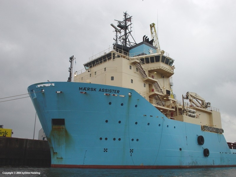
My 1st ship for the 2nd Period of Seagoing Service was the Anchor Handling Tug / Supply Vessel "Maersk Assister". The ship, built in 2000 in Stralsund, Germany, is one out of a series of 4 of A. P. Moller's biggest and strongest AHTS vessels on Danish flag. It is equipped with the world's strongest Anchor Handling Winch, capable of pulling with up to 700 tons! Principal data are as follows:
- Vessel type: Anchor Handling Tug / Supply Vessel
- Built at: Volkswerft Stralsund, Germany
- Year of construction: 2000
- Length: 90,31 meters (296,3 feet)
- Breadth: 23,00 meters (75,5 feet)
- Max draft: 7,80 meters (25,6 feet)
- Loading capacity (deadweight): 4740 tons
- Main Engines: 4 * MaK 9M32 4-stroke diesel engines
- Main Engines output: 4 * 5870 HP (= 23480 HP)
- Bollard Pull: 278 tons
- Max speed: 16,2 knots
- Port of Registry: Nordby, Denmark
The following pictures are all taken by me, Ebbe Holsting, and are copyrighted. However, should you wish to use them in any way please contact me for permission. Thank you!

|
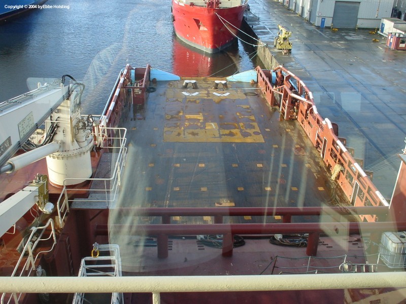
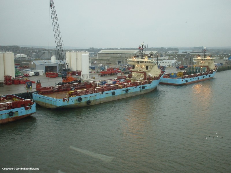
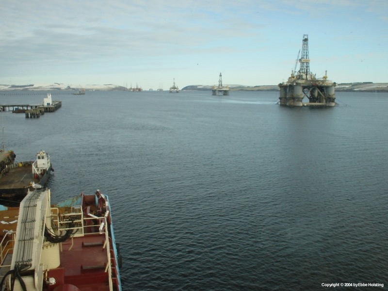
At berth in Aberdeen, Scotland this is where I embarked the ship on January 8. Plenty of AHTS vessels in the harbour due to the fact that the number of jobs for AHTS vessels is quite limited during the winter. We spend half of January at berth, but from the middle of February things got going and the number of jobs increased. We were hardly ever off-hire more than a day during March. |
|
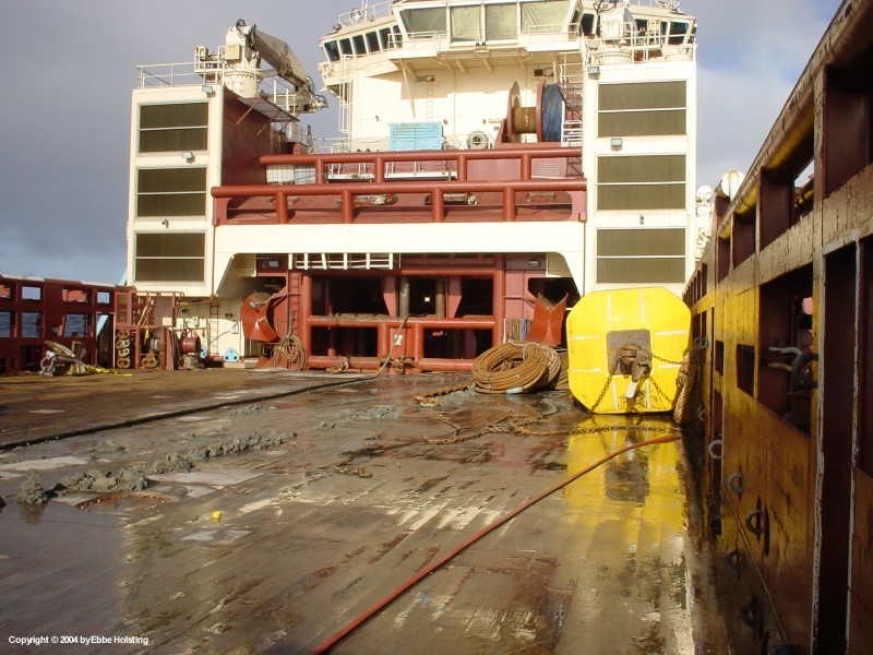
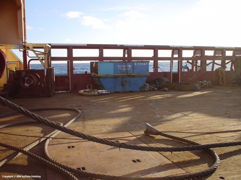
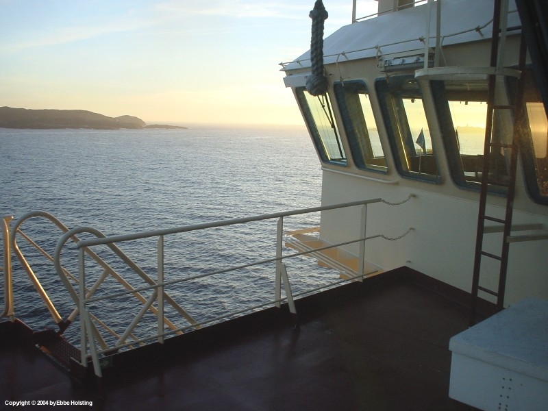
The main deck of the ship is made of steel covered with wooden planks. This is to make the deck stronger as wood is more shock absorbent than steel, and also lighter. Furthermore it also accepts wear better than steel. The small squares spread out are so-called strong points to which deck cargo can be welded etc. |
|
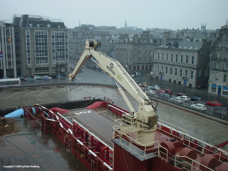
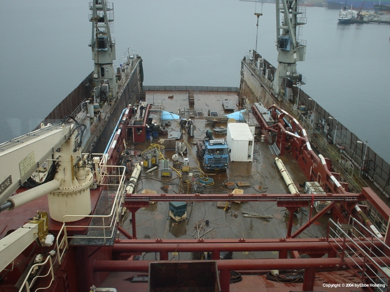
Here we are berthed almost in the center of Aberdeen, moored alongside of a smaller Norwegian supply vessel (we only had the stern alongside). We had two cranes like the one shown in the picture, each able to lift 14 tons. They were used for all kinds of operations, for instance loading of stores and provision, storing of cargo on the top of the winch garage etc. |
|
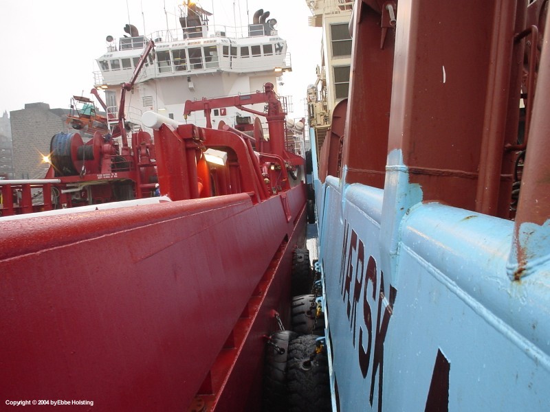
Another picture from the same situation, this one showing how we were moored alongside the other ship. The tyres on the sides of the ship are fenders. The quays in Aberdeen are not equipped with fenders, so they were very needed. |

|
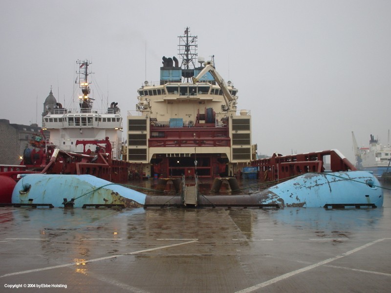
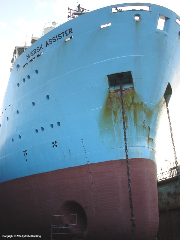
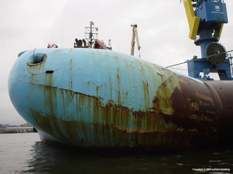
Taking a walk on the quay I had the chance to take some pictures of the ship from the outside. The two symbols looking like and X under the ship's name indicate that the ship is equipped with 2 stern thrusters for propelling the ship sideways. The manouverability of the ship was outstanding due to its powerful thrusters, main propellers and effective rudders. |
|
Having a look at "the lady" from abaft. The two A shaped structures to each side of the gangway are the Rope Guides used when towing or working with anchors. The steel wire from the main winches, when working as mentioned, runs out over the stern and into the water through these guides, thereby restricting movement of part of the wire that is on deck. |
|
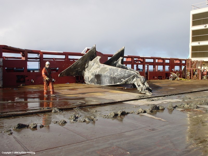
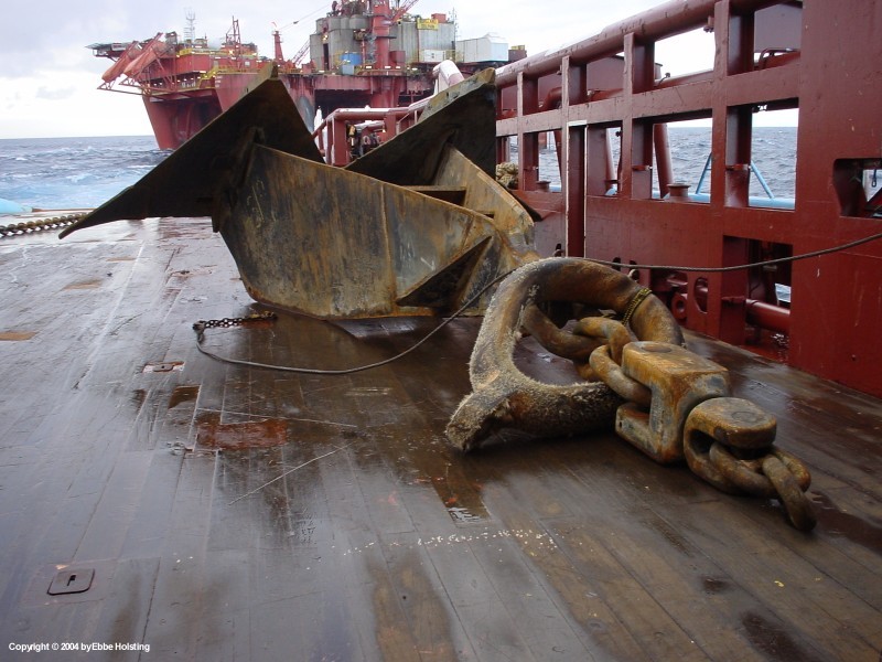
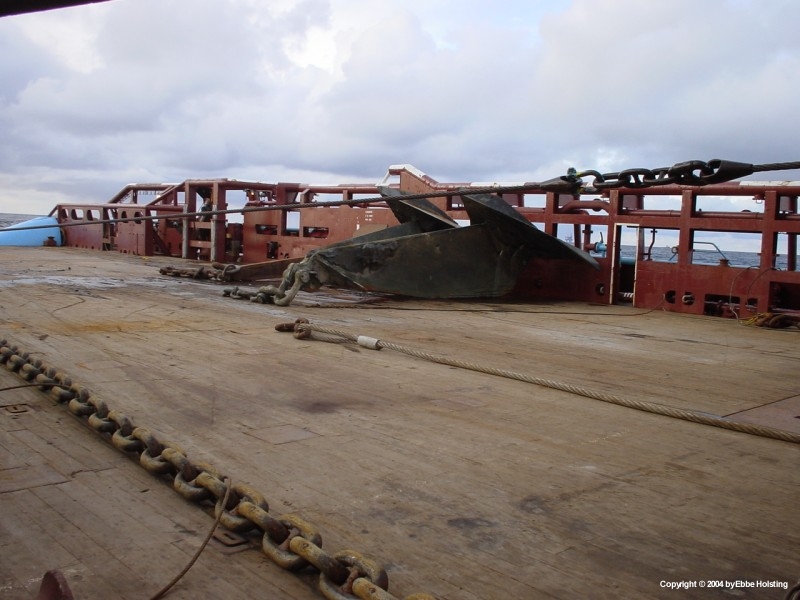
A 22 ton heavy anchor of the Stevpris type, used for mooring semi submersible oil drilling rigs. This was the biggest anchor we worked with during my 3 months on board, usually oil rigs are moored with 16 tons achors. A typical oil rig is moored with 8 anchors. |
|
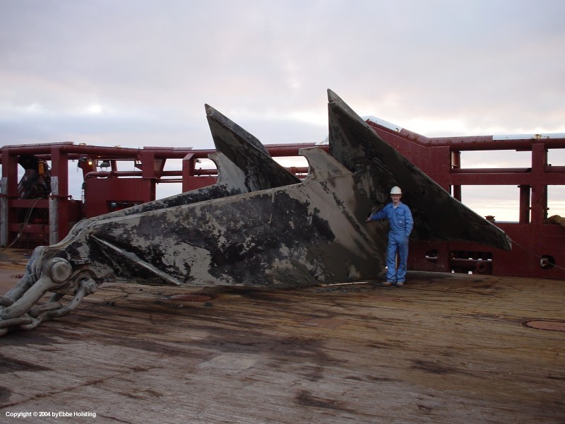
Just for the sake of comparison I had this picture taken where I am standing beside the 22 ton anchor. Anchors like this one could, when deployed correctly, withstand a tension of more than 700 tons! When the anchor is deployed on the bottom, the oil rig heaves in on the anchor chain until the tension reaches a disered value. The high tension on the anchor will cause it to dredge itself several meters down into the seabed. |
|
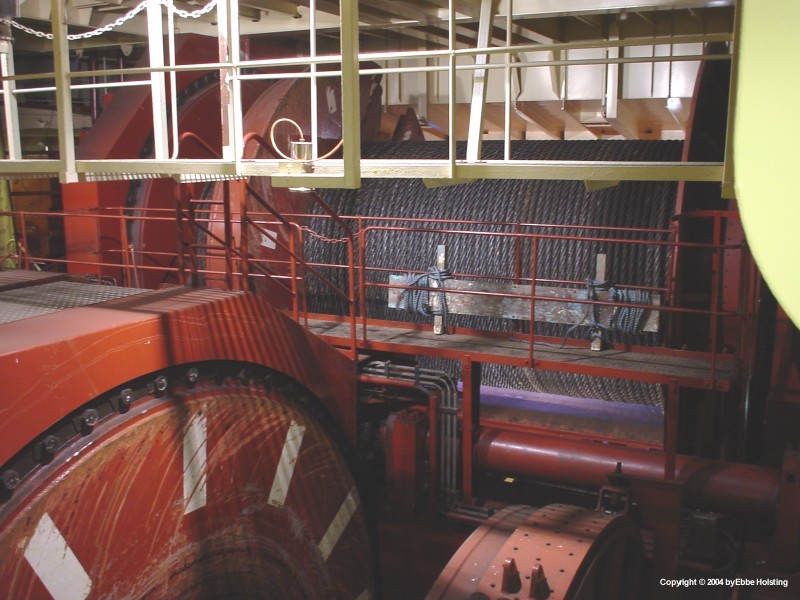
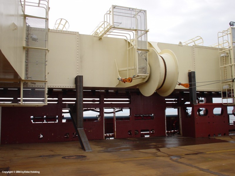
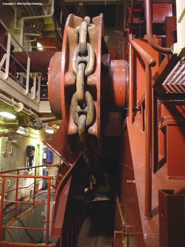
A look at the main anchor handling winch cabable of pulling up to 700 tons! The ship is equipped with one anchor handling winch and two smaller towing winches. The winches are all controlled from the bridge, and through a series of videocameras all winches can be supervised from several angles via monitors on the bridge. |
|
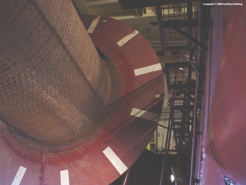
The winches are driven by up to four direct current electric motors. Through a number of couplings the three winches can be configured to run with one or more of these motors. When paying out heavily loaded wire the motors naturally do not consume power. Instead they generate power, the largest part of which is cunsumed by a number of ballast resistors. A small amount of the generated power can also be directed through a converter to the ship's Main Electrical Switchboard. |
|
We berthed at Aberdeen several times, and one of the times we had company by three of A. P. Moller's supply ships of the F-type (Maersk Feeder, Maersk Fighter and Maersk Forwarder). Where Maersk Assister is an Anchor Handling Tug / Supply Vessel these three vessels are Platform Supply Vessels. These vessels sail stores and provisions to and from oil production platforms at sea, and are neither powerful enough nor equipped for towing or anchor handling. |
|
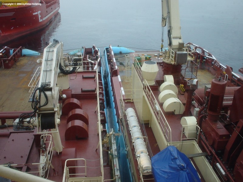
Looking forward from the main deck. In the middle of the picture a single wire rope is coming out through the so-called "crucifix" from the winch garage, where the 3 main anchor handling winches are placed. The yellow box to the right is a bouy used in connection with rig mooring systems. The three large black rectangles to each side of the crucifix are the air intakes for the engine room ventilation. |
|
Same situation as above, though this picture was taken a fiew minutes before. Achiever was moored alongside our starboard side, and furthermore we were moored alongside on of the Norwegian vessels, so we were moored three vessels side by side. Notice some structural differences between the two vessels on the aft part of the deck, most of them due to the fact that Maersk Assister has been equipped with an A-frame and Achiever hasen't. |

|
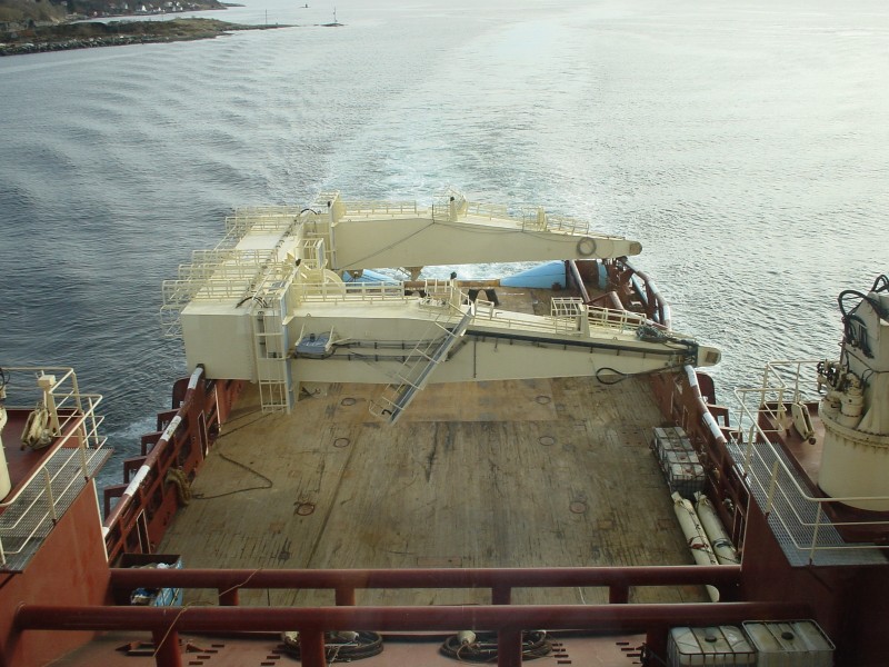
In february we were chartered to do a rigmove together with two norwegian boats and the Maersk Achiever, a sister ship to Maersk Assister. Here Achiever is leaving for the oil fields, and we followed soon after. A. P. Moller has a total of 4 ships like Maersk Assister in the Danish ship registry, and 2 more are to follow for the British ship registry. |
|
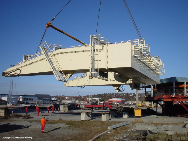
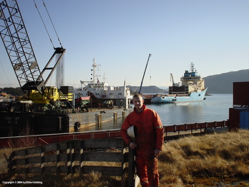
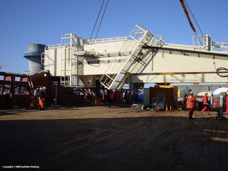
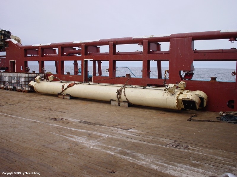
At Hinna, Norway (Hinna is near Stavanger) the ship's A-frame had been stored for several months, but a new job for Maersk Assister required that is was mounted again. The A-frame is used for lifting large equipment out over the stern and into the sea. The job that the ship has been chartered for is pipeline dredging (where underwater pipelines are plowed into the seabed), and the A-frame will be used for deploying a giant 140 ton plow over the stern. |
|
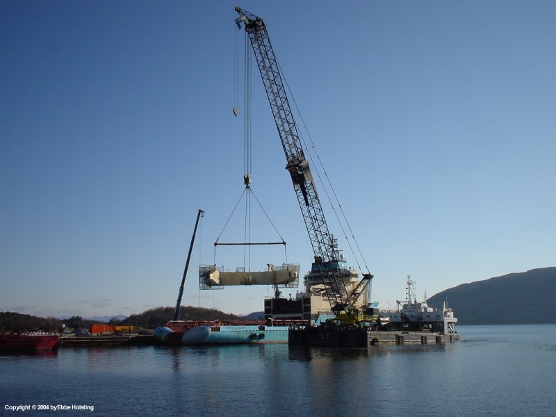
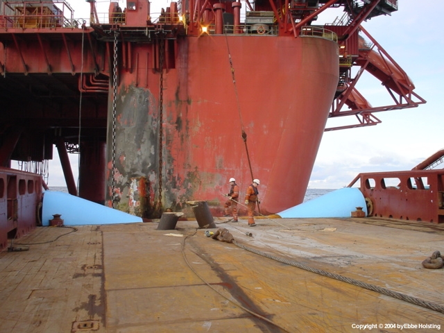
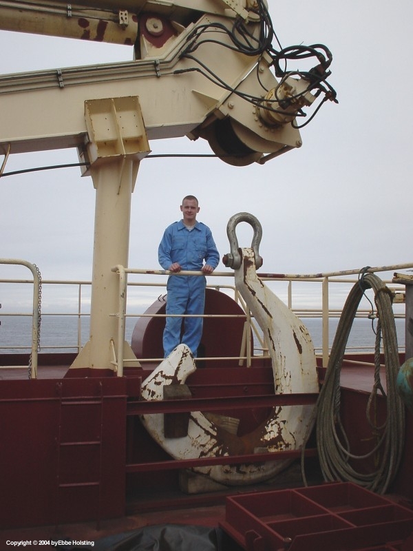
The A-frame was lifted onboard by a huge floating crane, as seen to the left in the picture. The A-frame weighs about 140 tons, and is able to lift 200 tons out over the stern! That's me in the picture. |
|
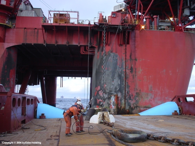
Another picture of the floating crane. The crane was equipped with its own propulsion, so all the manouvering was done by the crane itself. The frame was to be transported to Fredericia, Denmark laying on the cargo rail. In Fredericia it would then be mounted on the ship, but first the ship had to be fitted with new frame foundations since the frame had to be placed higher and longer abaft in order to handle the enormous plow, which happens to be the biggest plow in the world! |
|
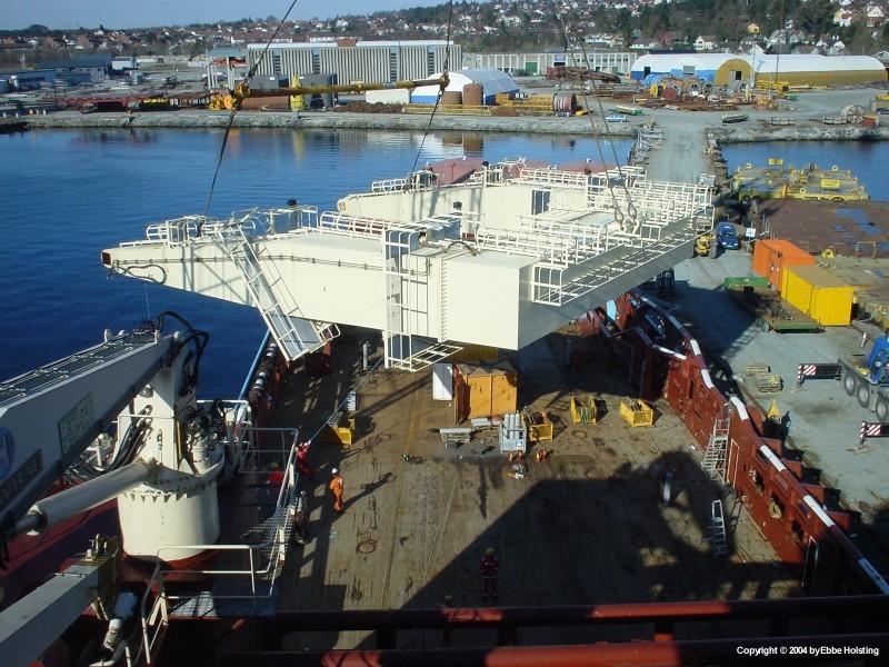
The A-frame is here almost landed on the ship. Notice the car tyres covering the cargo rail to the left. This naturally to support the A-frame when laying on the railing. Workers from a company ashore came onboard and constructed a series of steel reinforcements to keep the frame in place when positioned on the ship. They did all the work, supervised by our ship officers. |
|
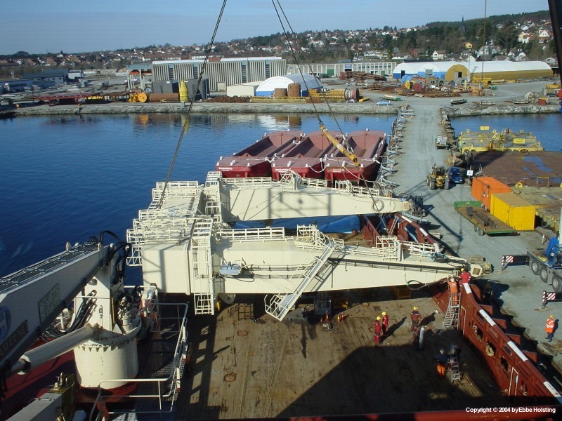
Touchdown! Here the A-frame is landed on the cargo railing and the workers from ashore started welding the reinforcements onto the deck and cargo rail. The frame was later lashed by our ships assistants with chains and pulleys. |
|
There was no text books or official examples of how to transport the A-frame, so this solution was worked out by teamwork between the crew of the ship and the A. P. Moller main office back in Copenhagen, Denmark. Actually the solution was perfect, as the A-frame fitted perfectly onto the aft most part of the cargo rail. |
|
The A-frame fully lashed and ready we took off and set course for Denmark where the frame would be unloaded and the ship drydocked for minor repairs and structural changes. These changes would be paid for by the company chartering the ship for pipeline dregding, as the changes were made only to fit the requirements for the job. |
|
This picture shows the reinforcements welded onto the strong points in the main deck. Similar steel structures were welded on the outside of the frame prohibiting movement in any direction. The huge wheel on the frame supports the wire rope carrying whatever equipment the ship is working with out over the stern. |

|
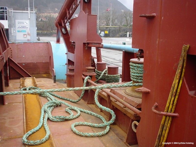
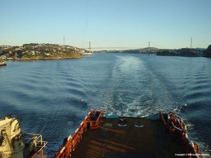
The stern of the ship, here berthed at Bergen, Norway. The blue rounded sides are called "whalebacks", and the round rusty tubes in the middle are the stern rollers. When wire rope runs into the water from the ship these rollers will be turned by the wire (if the weight in the wire is great enough of course). This is to prevent wear to wire ropes and the ship. |
|
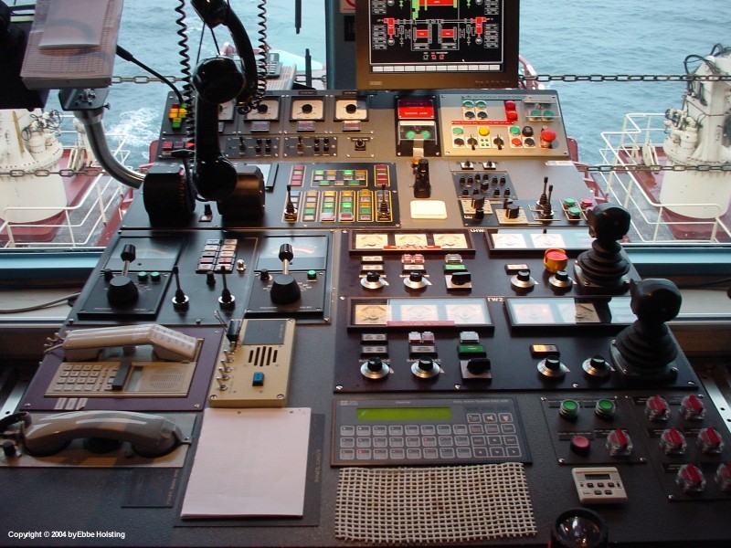
The controls on the aft part of the bridge. These are used mainly when anchor handling or when doing other work involving the main winches. The two handles to the right control the two towing drums on the main winches, and the two sticks to the left control the main rudders when steering manually. In front of these handles we see the pitch controls for the main propellers. |
|
A different angle yet still in the aft part of the bridge. The two computer screens in the middle are the Dynamic Positioning computers. Dynamic Positioning is able to automatically control all thrusters, main propellers and rudders in order to keep the ship at an excact geographical position. It even corrects for the force of wind and current as well as sea conditions. |
|
A 16 ton Stevpris anchor lifted on board from the seabed. The ring around the anchor chain is called the "Chaser Ring", and is used to catch the ancher on the bottom. When the oil rig is moored the chaser ring os pulled back up the anchor chain all the way back to the rig where the "chaser wire" (connected to the chaser ring) is kept on board while moored. When pulling up an anchor, the ship receives the end of the chaser wire and sails away from the rig in direction of the anchor, dragging the ring along the anchor chain. When the ship reaches the position of the anchor it heaves on the anchor winch, thereby lifting the anchor off the seabed and onto the ship's deck. In stead of the rig having the loose end of the chaser wire, this can also be bouyed off above the anchor. |

|
A Stevpris anchor fresh up from the seabed. The anchor chain is seen locked in the hydraulic stopper called the "Shark Jaws". The shark jaws carry the load of the anchor chain, enabling the ship to pay out slack wire and chain on deck. This is used with connecting shackles, anchors and other equipment to anchorchains, or when working on the anchor chain in general. Safety procedures perhibit crewmembers from entering the main deck whenever wires or chains are under tension. |

|
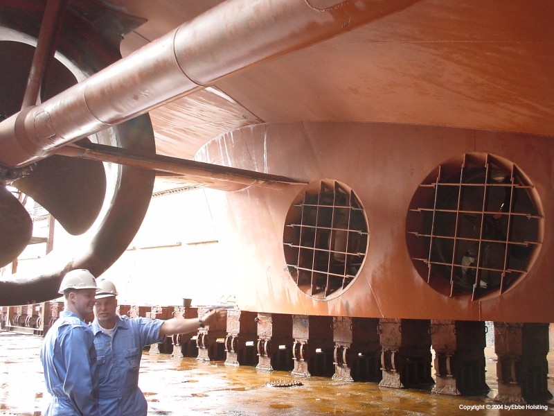
During docking in Fredericia, Denmark, the anchors were lowered off to the bottom of the dry dock so that also the anchor fairleads could be repainted. I am standing beside the port anchor. Each anchor weighs 6� tons. Not the strange textures in the vessel's red bottom paint. The entire hull was cleaned with high-pressure fresh water, causing these funny textures in the old paint. The vessel was later repainted. |
|
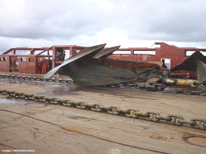
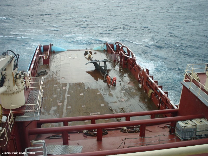
A typical anchor handling operation: an oil rig mooring anchor being hauled up on deck. The anchor chain should have been laying on top up the anchor in stead of beneath it, but a lot of factors have to be right in order for an anchor to be retrieved correctly. Actually, anchors coming on deck with everything in the right place is more of an exception than a rule. I refer to my anchor handling procedure for a despcription on how such an anchor is taken up from the seabed. |
|
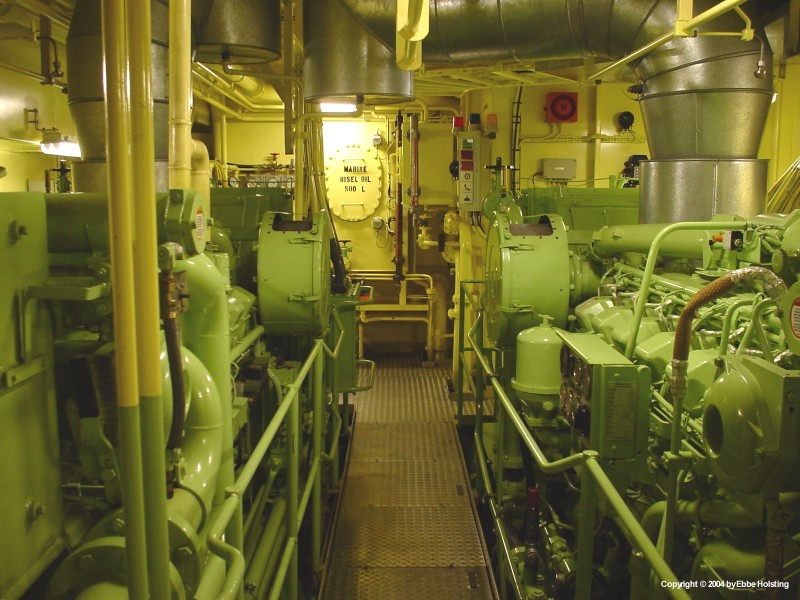
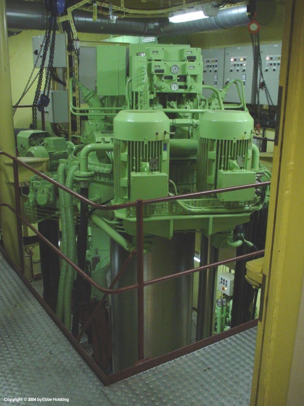
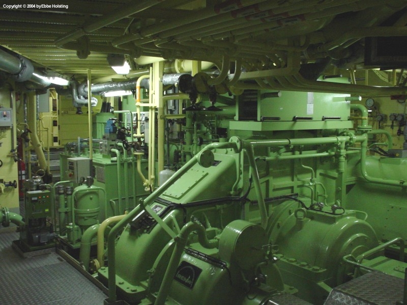
The auxilliary engine room of Maersk Assister, howsing two 12 cylinder four stroke diesel engines driving one elctric alternator each. On Maersk Assister the auxilliary engines are only used when at berth. When at sea the needed power is supplied by the four shaft generators driven by the main engines. |
|
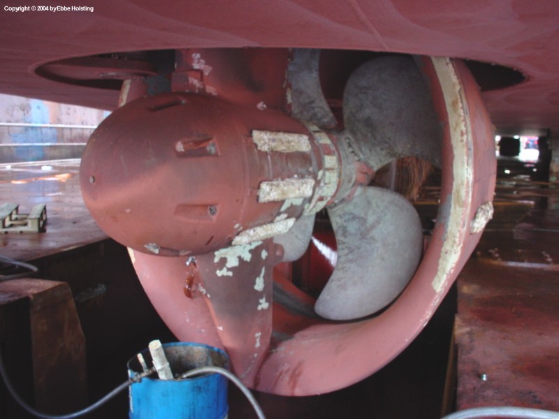
Another picture shot while the vessel was docked, this one showing the azimuth thruster. An azimuth thruster is a thruster able to turn 360° horisontally so that thrust can be applied in any direction. This azimuth thruster was even retractable, meening that in could be lifted up into the hull of the ship by a set of hydraulic cylinders. |
|
Viewing the azimuth thruster from "inside", we se the thruster in housed position. The two electric motors in the foreground turn the azimuth. The main electric motor propelling the thruster is located on the bottom of the engine room, and is engaged to the thruster by an automatic clutch once the thruster is fully extracted. |
|
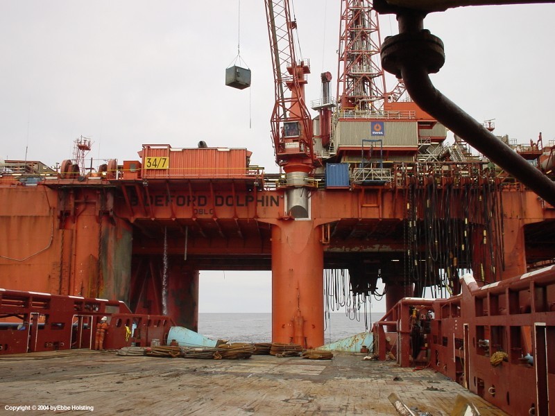
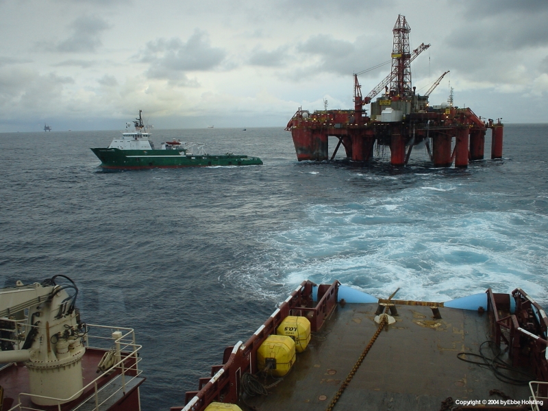
Working at the semi submersible drilling rig Bideford Dolphin, we receive some equipment prior to commencing the actual move of the rig. When this close to the rig the ship is manouvered by hand by either the Captain or the Chief Officer. Occasionally the First Officer gets a go at it too. |
|
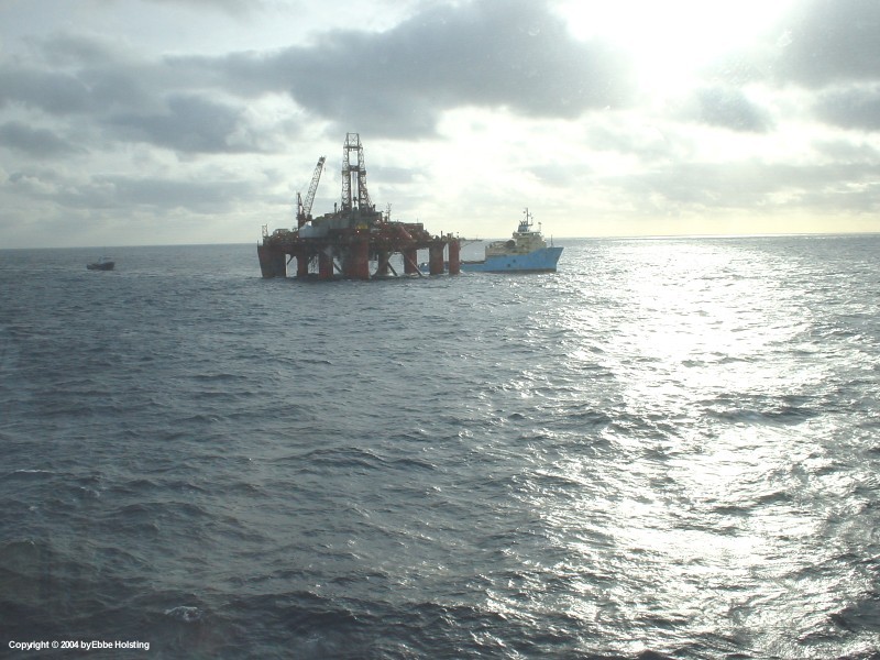
Moving Bideford's sister rig, the Borgland Dolphin. On this job we worked together with two other vessels, namely the Maersk Achiever and the Normand Master. The semi submersible drilling unites are moved several times a year and carry out the initial drilling at a new oil production site. After drilling, the rig is moved away, and a production rig is placed above the drilling site. The production rig then starts pumping up the oil and destributes it either to shore via a pipeline or to one or more tankers moored nearby via a set of pipes, tubes and mooring buys. |
|
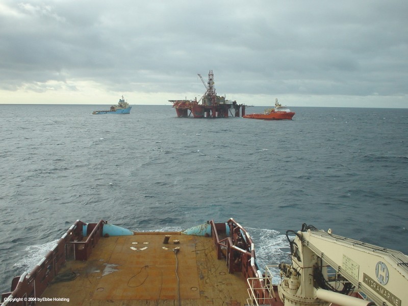
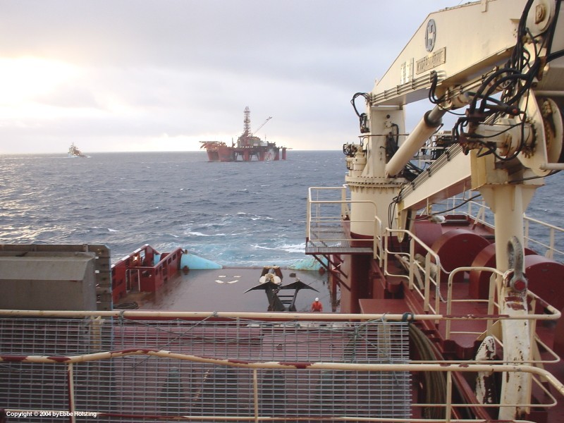
A lot of time is spent waiting when moving an oil rig. Here we wait while the Maersk Achiever approaches Borgland Dolphin in order to receive either some equipment or a chaser wire before commencing an anchor pickup. Of safety resons only one vessel is allowed to approach the rig at one time. |
|
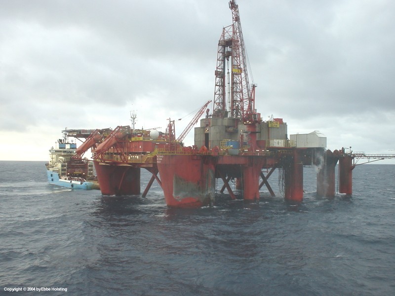
With the Achiever soon out of the way we approach Borgland for picup of the chaser wire. One the chaser wire is on board we will "chase out" the anchor wire and haul up the anchor. Once again I refer to the anchor handling procedure for a detailed description on what actually happens during anchor handling. |
|
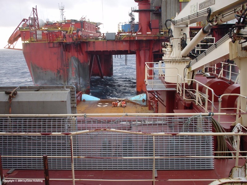
Up close to the rig the chaser wire has now been locked in the shark jaws and the vessel's work wire will then be connected to the end of the chaser wire before chasing out is commenced. The ship has four Ships Assistants on board at all times, and when working at a rig they work in shifts of 6 hours, two men at a time. The third man in this picture is my fellow cadet Hasse. |
|
Having chased out the anchor and pulled it on board, the work wire is disconnected from the chaser wire. Note how this anchor has been retrieved correctly with the anchor chain resting on top of the anchor bewteen the two legs. |
|
Tough manual labour as the wires are connected and disconnected. Mind you, the shackles found on supply vessels weigh 50 kilos! This image also shows how the anchor wire is positioned correctly on top of the anchor. |
|
With the anchor chain pulled off the anchor and to the stern of the vessel, the anchor is now towed abow with the tugger winches for storage until deployment at the oil rig's new drilling site. Note that the chaser ring has been disconnected from the chaser wire and is stored together with the anchor. The free end of the chaser wire can be seen laying on deck in front of the winch garage. |
|
This version of the anchor retrieval varies a bit from the one described in my anchor handling procedure. Usually the anchor is not disconnected from the anchor chain but insted just ferried back to the oil rig where it is stowed on the anchor bolsters designed for that purpose. So in order to be able to get a hold of the anchor chain again, the free end of the chaser wire was connected to the free end of the anchor chain, and the other end, as shown in this picture, was then handed back to the oil rig via the oil rig's crane. |
|
Preparing to tow the oil rig in one of its anchor chains, the opportunity of discharging a spare chaser ring to the rig is taken while close to the rig's crane. |
|
Now slowly towing the oil rig together with the supply vessel Bourbon Surf. The careful reader will notice that this ship was not part of the operation earlier. This is due to the fact that we actually moved the Borgland Dolphin two times during my time on board, and this picture was taken the first time, the others the second. For the sake of understanding how rigmoves work, however, I decided to include this picture on my homepage. |
|
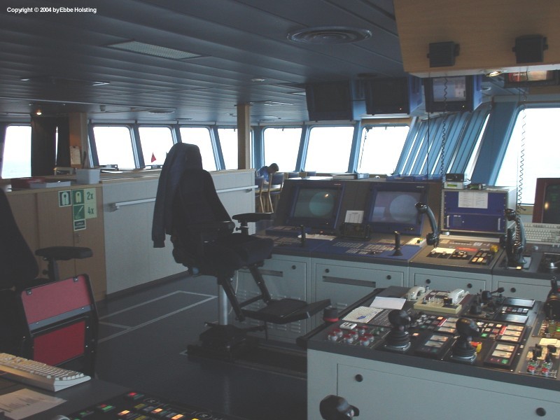
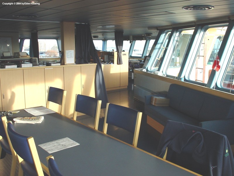
The wheelhouse on the Maersk Assister, also called the "bridge". The bridge is actually relatively large on supply vessels, since the ship is equipped with two manouver stands, one on the front side of the bridge and one on the side turning aftwards. The aft one is used when anchorhandling. |
|
Picture taken from the same spot as before, except this time I have turned 30° to my left. The aft manouver stand is seen in the left side of the picture. |

|
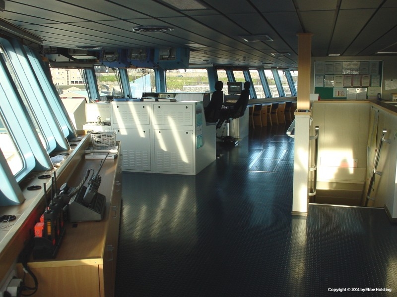
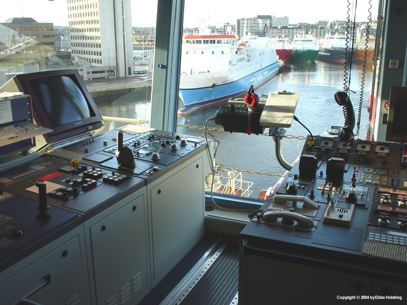
A view of the foremost manoeuvre console. The ship is manoeuvred from this position during normal sailing (when sailing ahead). The aft manoeuvre console is used during anchor handling procedures and other work related situations. The bridge equipment includes two radars, an electronic navigational chart display as well as controls for main engines, thrusters etc. |
|
Back on deck, we here see a lose piece of steel wire rope. Notice the broken wire socket! This socket broke during anchor handling operations, causing the wire rope's end to fly into the back end of the winch garage with a large BANG. Due to strict safety procedures no crew members were harmed, and apart from the socket itself, nor was any of our equipment. The hatch in the deck leads to the engine room, and is used for lowering spare parts and stores into this department. |
|
Moored at Bergen, Norway. To the right one of the ship's capstans is visible. These capstans are driven by large electrical motors and are used both for mooring as well as anchor handling operations, where they are used for moving heavy equipment around on the deck together with the tugger winches, which are located on the forepart of the working deck. In the lower left side of the picture we see the remains of the socket for the once-fitted A-frame. At this time the ship was scheduled to be fitted with the A-frame again, but it was to be mounted on a new socket, so the old socket was cut off. |
|
Not all work carried out by AHTS vessels involves large winches and powerful hydraulic machinery. Here the deck is loaded up with equipment for a so called 'Cargo run', i.e. transportation of equipment out to an oil rig. Normally cargo runs are carried out by PSV vessels (Platform Supply Vessels), which are supply vessels not equipped with winches and hydraulic machinery used for anchor handling. They only serve as transport vessels, supplying the rigs with equipment and stores. |

|
A view into the rig chain locker in starboard side. Maersk Assister is constructed with two chain lockers for storage of rig mooring chain. Some oil rigs are not equipped with adequate storage space for all its mooring chains, and in this case the chain can be disconnected and stored onboard the supply vessel instead. |
|
Here we have approached the rig in order to offload a chaser ring with attached chain. (In this picture you can see the function of the chaser ring and wire). Note the end of the rig's anchor chain locked in the shark jaws. The chain is attached to the AHTS vessel's work wire from the anchor handling winch. The anchor chain can also be seen hanging from the winch onboard the rig. In this situation, the rig's anchor has been removed for storage onboard the AHTS vessel, and the rig will receive the end of a wire rope connected to the anchor chain instead of having the anchor resting on the bolster. |
|
The aft end ("opening") of the winch garage, on the foreward most part of the working deck. Notice how the construction leaves three openings, a wide one on top for the work wire from the anchor handling winch, and two smaller openings below for each of the less powerfull towing winches. Notice how the work wire from the anchor handling winch extends from between two vertical rollers. These are the "spooling devices", wich can be moved from side to side in the winch opening by means of hydraulics in order to facilitate correct placement of the wire on the winch drum. |

|
Delivering supplies and provision to the Jack-up rig "Ensco 71". We had also been chartered to move this rig, but first the rigmove was postponed due to bad weather conditions, and after a week it was ultimately cancelled since the weather didn't improve. During the waiting time we sailed to Esbjerg, Denmark for change of crew. I stayed onboard though together with my fellow cadet. In Maersk Supply Service, the sailing period onboard vessels enganged in the North Sea is 5 weeks, followed by 5 weeks vacation ashore. |

|
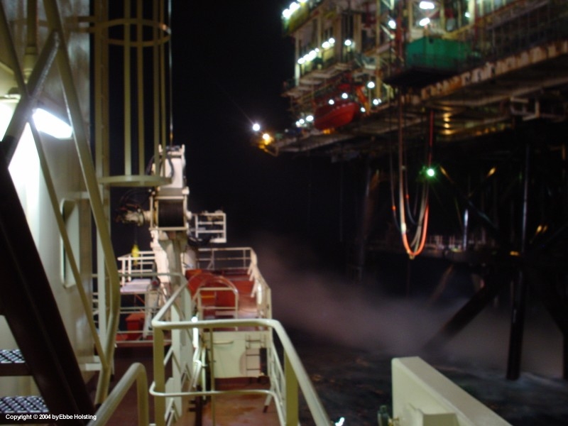
Completing a "cargo run" (delivery of supplies, equipment and provision) to a larger oil production platform. The large flame visible in the pictures is called the "flare". Excess gasses escaping from the drill site are burned off here. Note that in the offshore industry there is a difference between an oil rig and an oil platform. Rigs are either the semi-submersible oil rigs moored by anchors as described on this site or jack-up rigs similar to the Ensco 71 above. Jack-up rigs are fitted with 3 subtractable legs which extend to the seabed when the rig is in place. Platforms, on the other hand, are larger units usually constructed on-site with a fixed support resting on the seabed. |

|
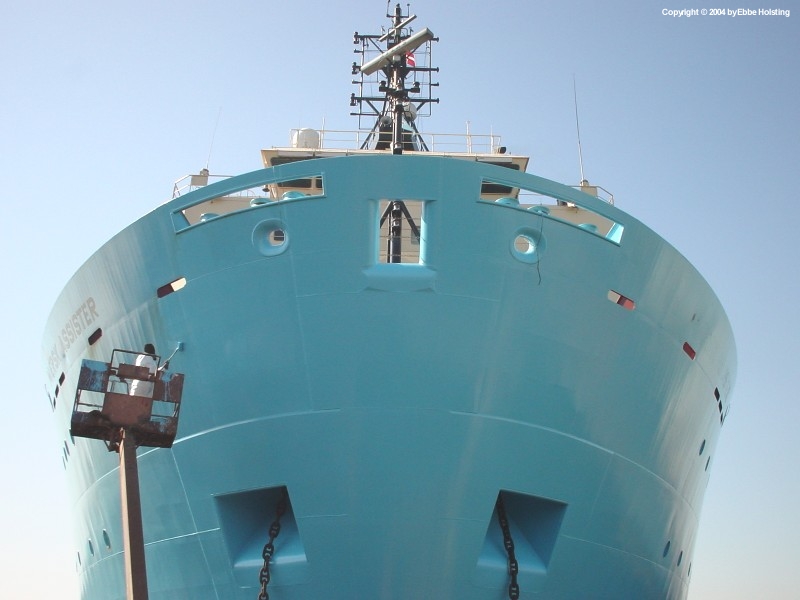
Viewing the bow of the ship from the navigation bridge (wheelhouse). |
|
The monthly test of the MOB boat (MOB = Man Over Board) is always a great opportunity to get some pictures of the ship. Note the symbols on the side of the ship indicating the presence of a bow thruster and azimuth (retractable) thruster. The ship is also fitted with two stern thruster in the aft part of the hull. AHTS vessels are typically very manoeuvrable due to the many powerfull thrusters, the excess of main engine power as well as the fact that they are equipped with two main propellers. |

|
The vessel viewed from port aft quarter. The stern of the ship bears the marks of anchor handling work, with the paint scratched off on the whalebacks. The stern roller in the middle is rarely kept painted. |

|
Entering the dock, a socalled Floating Dock, in Fredericia, Denmark. The dock is actually afloat, and takes in large ammounts of ballast water so that it becomes submerged as seen in this picture. The vessel scheduled for docking the manoeuvres onto the submerged dock. When the ship is en place, the dock pumps out its ballast water, and thereby refloats, lifting the docked vessel out of the water. In the right side of the picture, a refloated floating dock can be seen. |

|
The vessel is now correctly positioned and the floating dock will start discharging its ballast water. The ship is supported by a number of wooden blocks, these are visible in a picture further down. |

|
Standing abow of the ship looking aft, we here see the grating covering the bow thruster. The bow thruster is driven by an electric motor delivering 1500 kW (2040 HP). The draft marks just to the right of the thruster opening give a good idea on how big the thruster really is. The wooden blocks supporting the vessel while in dock are seen here. |
|
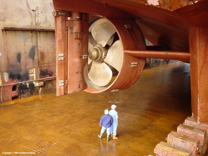
Docked in Fredericia, the Chief Engineer and Chief Officer are the first two to enter the dock and inspect the ship. Here we see the port side main propeller. The ring (nozzle) around the propeller optimizes the thrust power of the propeller, thereby giving the vessel a larger pulling force (larger Bollard Pull). The propeller itself is a Controllable Pitch Propeller, i.e. the propeller blades can be turned (pitch adjustment) hydraulically on the center hub. Speed adjustments and astern manoeuveres are then achieved by adjusting the pitch of the propeller, instead of changing the engine revolutions or direction of rotation. This greatly improves manoeuvrability. |
|
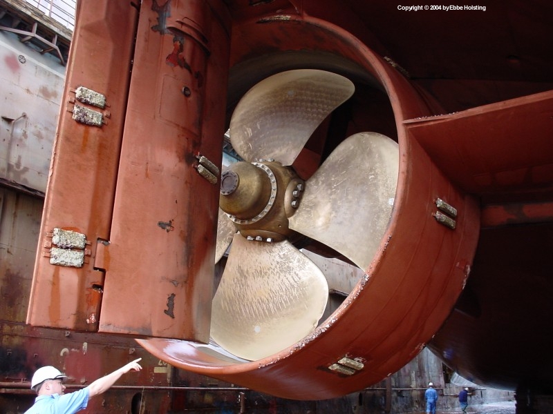
The grey blocks mounted on the rudder and propeller nozzle are zinc anodes. They prevent corrosion of the hull, as zinc corrodes more easily than steel. Also notice the flap on the aft end of the rudder. When turning the rudder, this flap turnes more than the rudder, thereby improving the efficiency of the rudder (popularly know as "Becker Rudders"). This is another reason for the great manoeuvrability of these ships. |
|
Looking aft from along the side of the ship with port side main propeller visible. When engaged, the propeller spins at about 120 revolutions per minute. Just visible to the left is the bilge keel, a long plate of steel protruding diagonally from the ship's hull which serves to dampen the rolling motion of the vessel. |
|
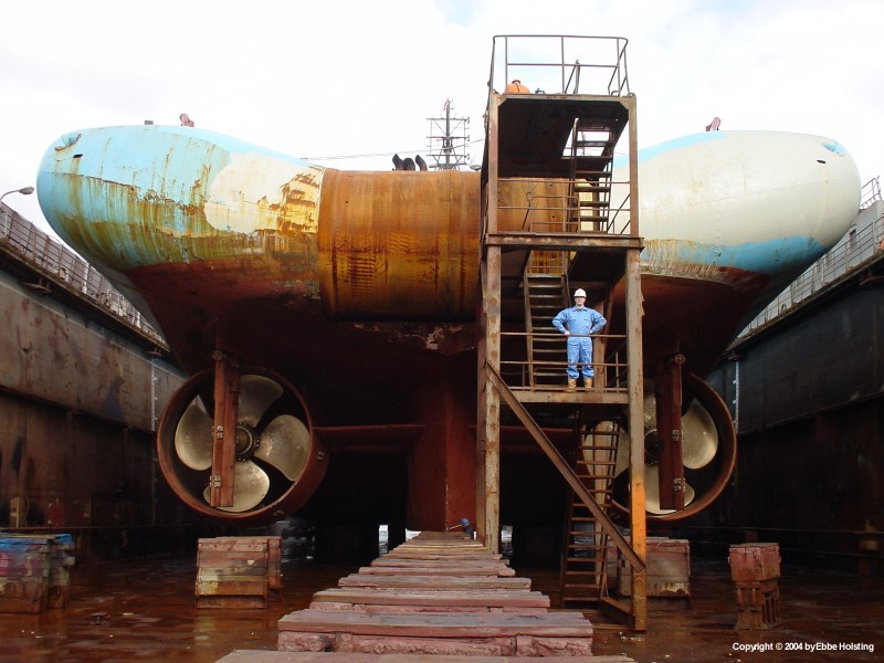
Starboard main propeller and the two stern thrusters. Having two thrusters in each end, apart from increasing available thrust, also provides redundancy, and in case of thruster fails, the other would still be available for position keeping etc. |
|
In Fredericia the ship was docked for main deck modifications and regular scheduled docking. My fellow cadet Hasse is standing in the stairway. The typical propeller layout of an anchor handling vessel can be seen here: 2 shaft-driven main propellers rotating in opposite direction and with a separate rudder each. |
|
In dry dock in Fredericia, Denmark for fitting of A-frame and ROV deck (ROV = Remote Operated Vehicle. An unmanned mini-submarine). An extra crane was also fitted on the starboard side of the working deck, it's foundation just visible in this picture. The hydraulic cylinders for the A-frame can be seen lying on deck. Days after this picture was taken, I signed off the ship. The A-frame was fitted due to the ship being contracted to a new charter, in which she was to engage in pipeline plowing operations using a 200 ton plow being dragged along the seabed. |

|
Supply vessels are the work horses of the sea, and are often modified to meet particular needs. In this case, the vessel had been chartered to perform underwater pipeline dredging and facilities for an "ROV" (Remotely Operated Vehicle = underwater robot) had to be installed in the shape of an extra deck. ROV's are fitted with cameras and robotic arms allowing specialized crews on the vessel to monitor and perform various subsea operations. |
|
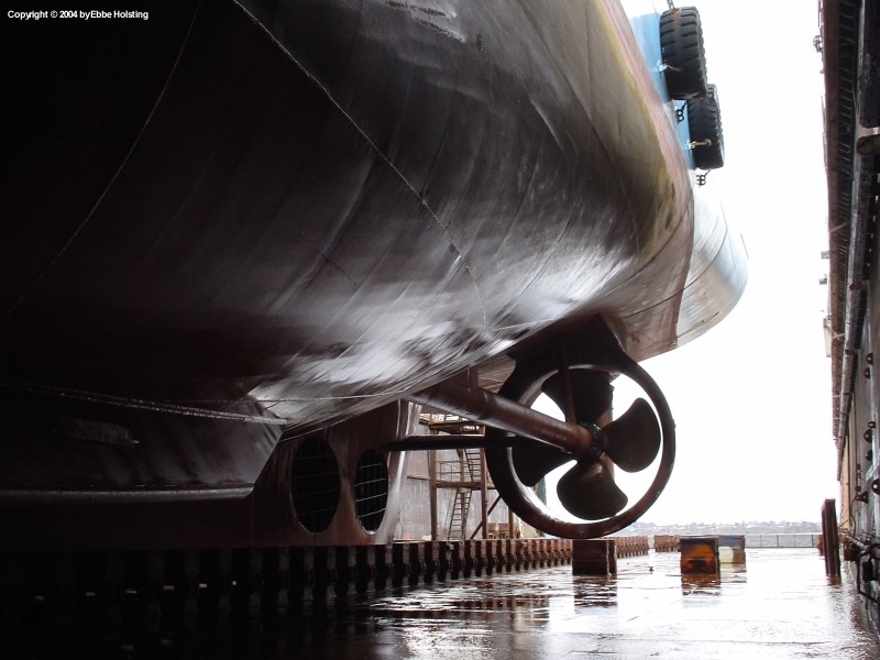
The vessel on dry ground in the floating dock in Fredericia, Denmark. The anchors have been payed off to facilitate painting of the hull. Notice the tunnel for the bow thruster. Usually a large grating covers each end of the tunnel, but they were removed in the dock so that the inside of the tunnel could be accessed for repainting. The draft marks give an idea of the size of the thruster (about 2 meters in diameter). Also notice that the vessel is NOT equipped with a bulbous bow. Some AHTS vessels do have a bulbous bow, but since the ships rarely need to go top speed, such a construction is not really necessary. |

|
Nice and shiny new paint being applied, standard procedure during a docking. The bottom part (painted red) was sandblasted before being repainted in order to remove old layers of paint. The red paint is a special silicone based paint that actually never dries out completely. When touched, it seems very greasy, and the purpose of this is to prevent "fouling" (growths of algee and other organisms) on the hull. |

|
|
|
|
|
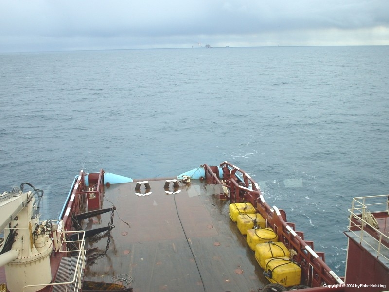
The grabler hook ready to be launched over the stern. The grabler is very similar to a fishing hook, and is used to pick up wires or chains laying on the seabed. The rig usually has an idea of where the wire or chain is located, and the ship then starts dragging the grabler along the seabed in this region by moving athwartships. The yellow boxes are bouys which can be used to mark off the position of a mooring anchor. |
|
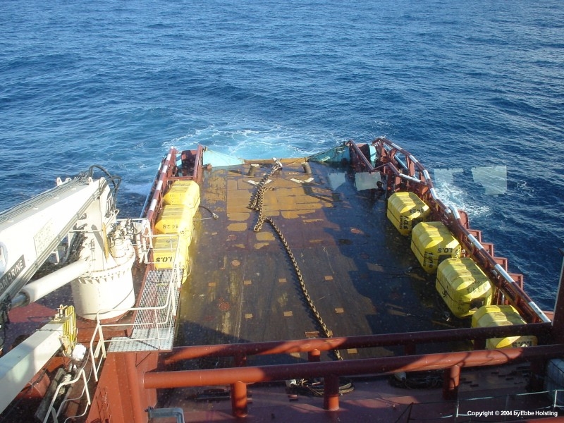
In this situation the grabler is connected to a length of chain instead of the usual wire rope. The function however remains the same. The wire or chain placed on the bottom could be the loose end of a chaser wire, (see the anchor handling procedure for details) or it could simply be an anchor with connected anchor chain placed on the bottom due to lack of onboard stowage space during anchor handling operations. |
|
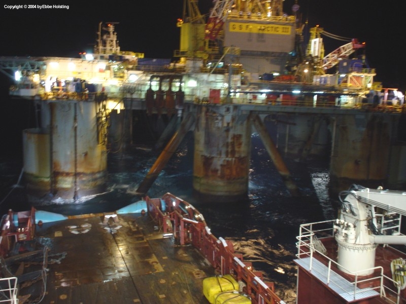
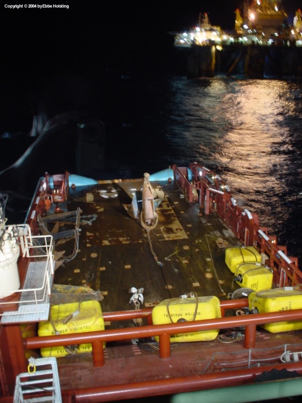
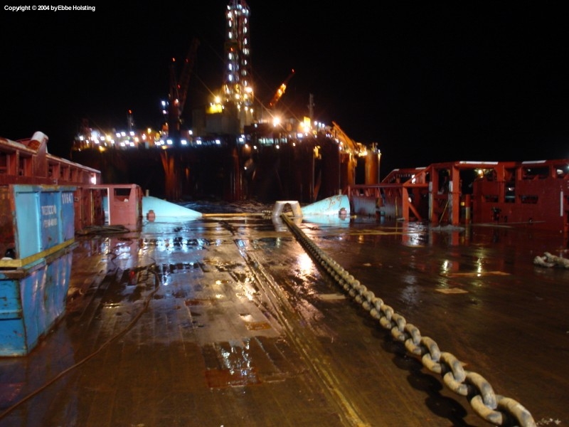
Anchor handling operations taking place during nighttime at the GSF Arctic 3 semi-submersible oil rig. Notice the smaller anchors loaded on the ship in the bottom left corner of the picture. These are socalled "piggyback anchors", which can be deployed in excess of the normal mooring anchors if these do not supply the rig with adequate holding power. |
|
A mooring anchor fresh off the bottom of the sea. In this particular situation, the anchor chain broke during the retrieval procedure (notice that there is no anchor chain connected to the anchor). The anchor was in a very poor condition: notice how the chaser ring has settled all the way down on the bottom of the anchor stock. The anchor is normally constructed so that the ring cannot pass this far down the stock. |
|
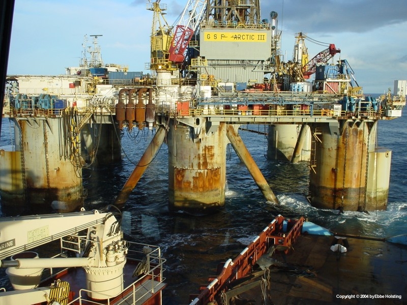
Still carrying out anchor handling at the break of dawn. A rig like this is typically moored with 8 anchors, two from each corner. In this picture the anchor chains and chain whinches are visible on the oil rig. On the chain on the far right, notice the thin chaser wire running from the surface of the water and up to the rig. This is the free end of the chaser wire. One end is kept on deck of the platform until hoisted down to the AHTS vessel be means of a crane, and the other end is attached to the chaser ring resting on the mooring anchor. Check out this page for further details. |
|
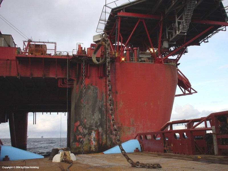
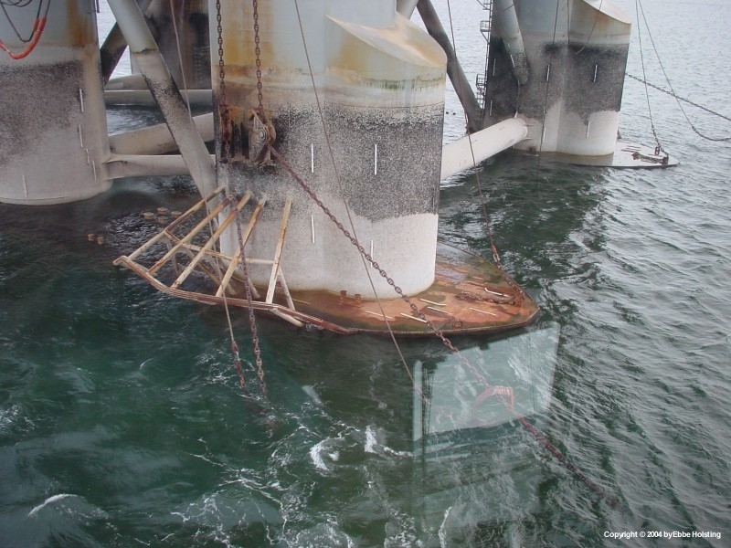
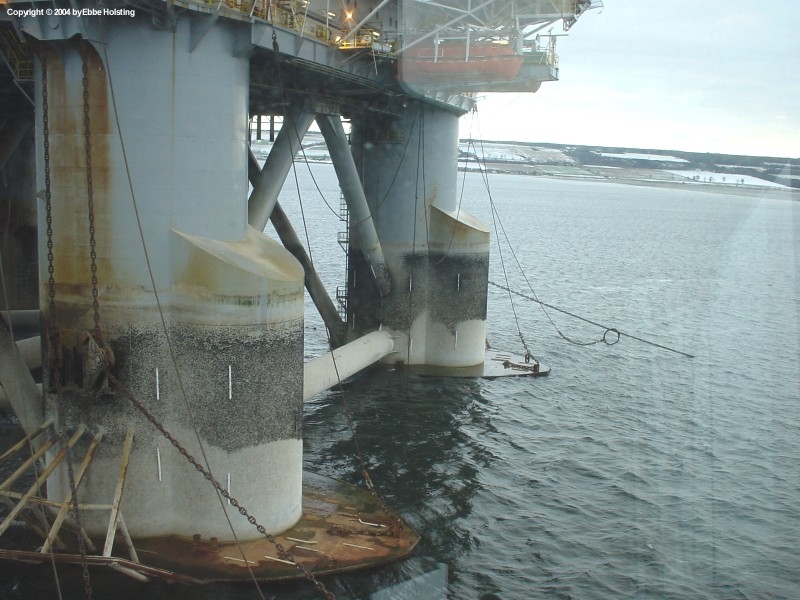
A very explanatory picture of the GSF Arctic 4 mooring system. The rig is here completely de-ballasted, and the anchor bolsters (the arrangement extending from the leg) are therefore out of the water. When the anchors are not deployed, they are placed on these bolsters by heaving in on the the oil rig's chain whinch. Also notice the chain fairleeds above the bolsters as well as the chaser ring resting on the chain of the deployed anchor, with the loose end being kept onboard the rig until the anchor is to be retrieved, at which time the chaser wire will be hoisted down to the AHTS vessel by means of a crane. |
|
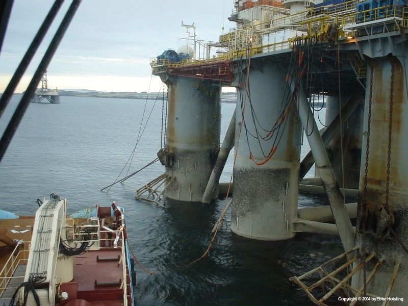
More bolsters, fairleeds, chains and chaser wires visible in this picture. This rig was moored in the Bay of Invergordon, Scotland, a bay that serves as a parking lot for oil rigs currently not in use. This rig, however, was to be reinstated and in this picture we are delivering fresh water to the rig by a flexible hose. |
|
Another view of the mooring system. Also notice the chains and wires mounted on the flat part of the hull, just above the water line. This is the "towing bridle", an arrangement in which the rig can be towed. Sometimes the rigs are just towed in an anchor chain, but for towing over larger distances it is recommended to use the bridle. |
|
The two enormous hydraulic cylinders for the A-frame, here loaded on deck for transport to the dock in Fredericia, Denmark where the A-frame was refitted. Hydraulic cylinders are known from for instance your cars, where they are used for holding up the trunk-lid. These are quite a bit larger though. |
|
A view out over the Bay of Invergordon in Scotland. As mentioned above, this bay was used as a parking lot for oil rigs currently not in use. To the right, the rig GSF Arctic 4, which we had been chartered to move out to a new location in the North Sea. |
|
Me standing above the "J-hook", a piece of equipment that can be used as a chaser ring, if one such is not fitted to an anchor due for retrieval, or if the chaser ring equipment breaks or is otherwise unusable. The hook is dragged across the anchor chain of the deployed anchor until it settles on the chain, and the chain can then be chased out as if using a chaser ring. Details can be found here. |
|
Located in the forward part of the whinch garrage we see one of the two "cable lifters", a wheel connected to the towing whinches for handling anchor chains. The wheel itself can be changed to fit different chain sizes, but since most rigs are moored with the same standardized size, we never had to change the chain wheel. From this wheel the chain can be guided into the chain locker for storage. The opening in the bottom left corner of the picture leads to the chain locker. |
|
The aft manoeuvre stand on the navigation bridge. From this position the ship is manoeuvrered during anchor handling operations. The joystick in the window can be configured in a number of ways. E.g. the main engines and thrusters can be "added" to the machinery controlled by the joystick, the vessel's heading can be locked to a certain course, and then you can move the ship in any direction, with a constant heading, by use of the joystick! You can also limit the joystick to operate the main propellers, and then control the thrusters manually. Each and every navigator has his own preferences on this account. |

|
The aft part of the two port side Main Engines. The output shafts from these two engines go to a reduction gear, a part of which is visible to the right. In the starboard side a similar setup is located giving the ship a total of 4 main engines connected in pairs to two reduction gears. Each gear then has an individual output shaft connected to a propeller, giving the ship two main propellers. All engines are connected to the gear by clutches, so either one or two engines can be engaged to each gear at any time. |
|
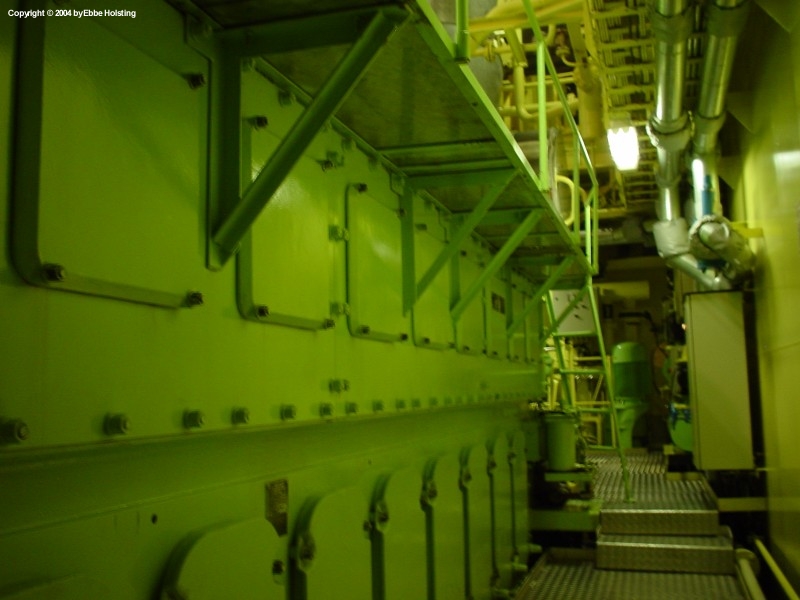
Looking aft along the side of Main Engine no. 1. All engines are of the same type, a MaK 9M32 9 cylinder four-stroke diesel engine with a cylinder bore of 32 centimeters and a maximum ouput of 5870 horsepower at 600 rpm. The reduction gears reduce these revolutions to about 120 rpm, which is the speed of the main propellers. Each of the two gears is also fitted with a Power Take-Out shaft, each driving two shaft alternators for power production at sea. When the main engines are not running, power is supplied from two smaller auxulliary diesel engines. |

|
Viewing the top of the two starboard main engines. The engines are turbocharged, one turbo visible in this picture just above the middle and to the right. The engines take in air directly from the engine room, the entire engine room being ventilated. The valve covers are visible on the engine top, housing the inlet and exhaust valves as well as the fuel injection valves (two inlet, two exhaust and one fuel injection valve per cylinder). |
|
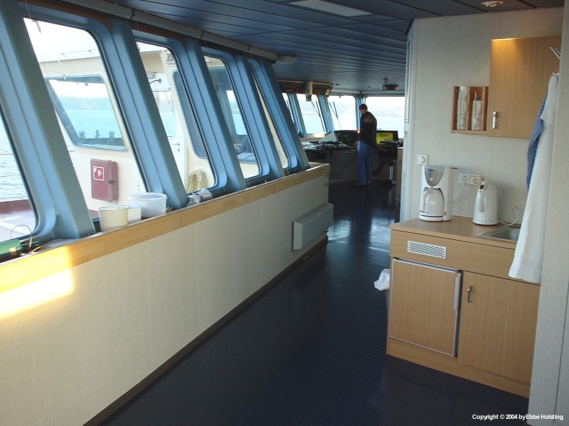
Another view from the the wheelhouse. Here I am standing in the port side bridge wing looking towards the forward manoeuvre stand. First Officer is seen at the stand, currently on watch and engaged in navigational duties. |
|
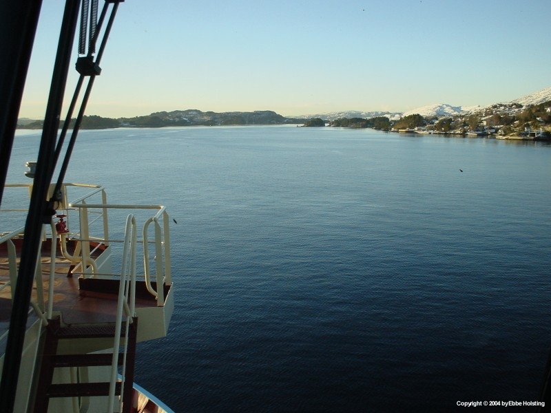
An outside view of the starboard bridge wing as we enter the waters between the Norwegian cliffs en route to Bergen, Norway. |

|
While berthed in Norway there was time to carry out some painting of the stern. Here an Able Seaman (Ship's Assistant) is manoeuvrering a paint barge into position so that he can reach the port side of the stern. About a month after this picture was taken we were docked in Fredericia, Denmark, and the entire hull was repainted, but maintenance of this sort is still important in order to prevent corrosion of the hull. |
|
Another view from the cargo run operation at a larger oil platform. The weather was a bit harsh, but we managed to complete the cargo transfers. Notice the number of hoses hanging losely on the side of the platform. These are for bunkering fresh water, fuel, lubricating oil, drilling water and other liquids. The Maersk Assister is also equipped with a number of tanks capable of holding such products for transport and delivery to oil rigs and platforms. |
|
Port side reduction gear viewed in full. In the bottom center we see the inlet shaft from Main Engine no. 2, and to the far right we see the inlet shaft from Main Engine no. 1. Between these two shafts we see the Thrust Bearing, which absorbs the longitudinal forces in the propeller shaft created by the rotating propeller. |

|
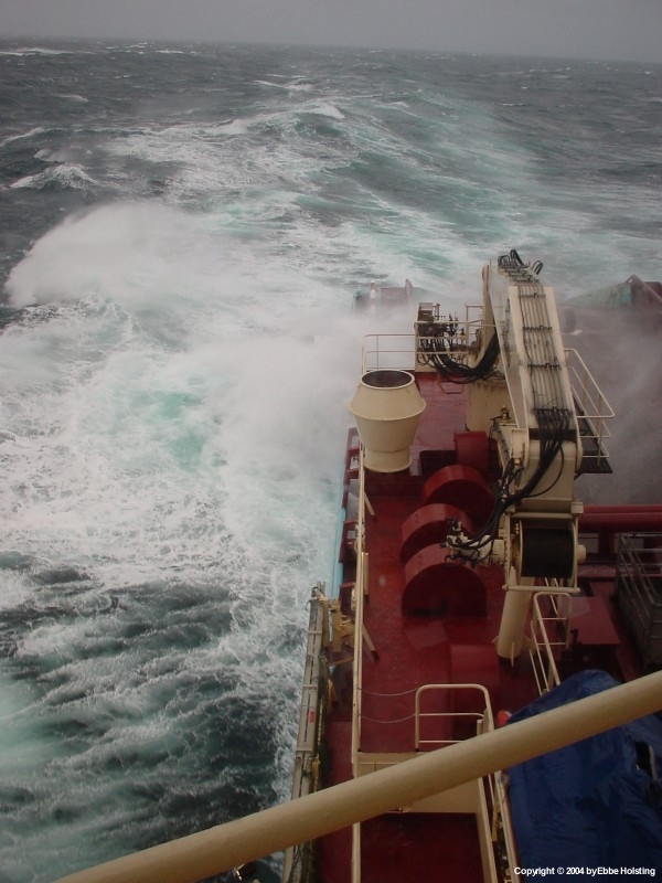
Rough seas in the North Sea, with seas washing over the working deck, carrying some plastic bags with them. In such conitions any presence on the working deck is not advisable, and is therefore refrained from. |
|
Seas washing over the cargo railing on the starboard side of the working deck. Winds in this situation reached a category 8 on the Beaufort scale (about 65 km/h). |
|
Transitting the inner fjords of Norway. The channels are narrow and the seabed is mostly rock, providing for some challenging navigation! |
|
The Norwegian fjords are nothing if not beautiful! |
|
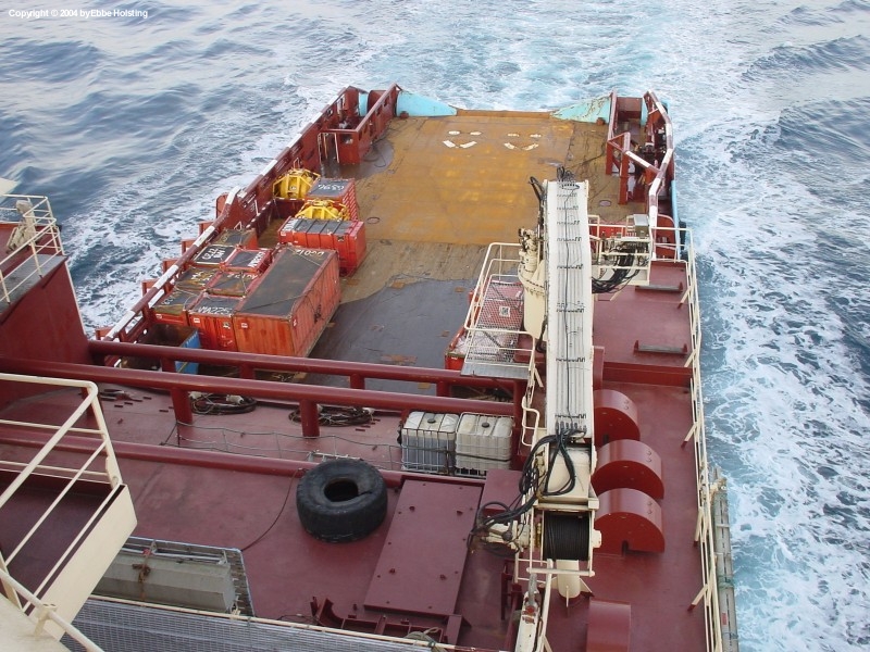
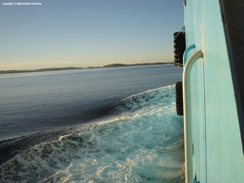
A view of port side from the main deck aft. The two tyres are not exactly pretty, but are commonly used as fenders on supply vessels. |

|
The Maersk Assister standby on the field with the sun setting. "Standby" is a term often heard on board offshore vessels, and covers any time when the ship is in some sort of on-hire-but-waiting position. This could be waiting for the rig to be ready for a rigmove or other work, for the weather to come down and allow work to commence or continue, for the rig to perform other work not needing a vessel etc. During standby the vessel can still have a number of duties, e.g. being on the alert for man-overboard rescue close to the rig if they have crew working over the side etc. |
|
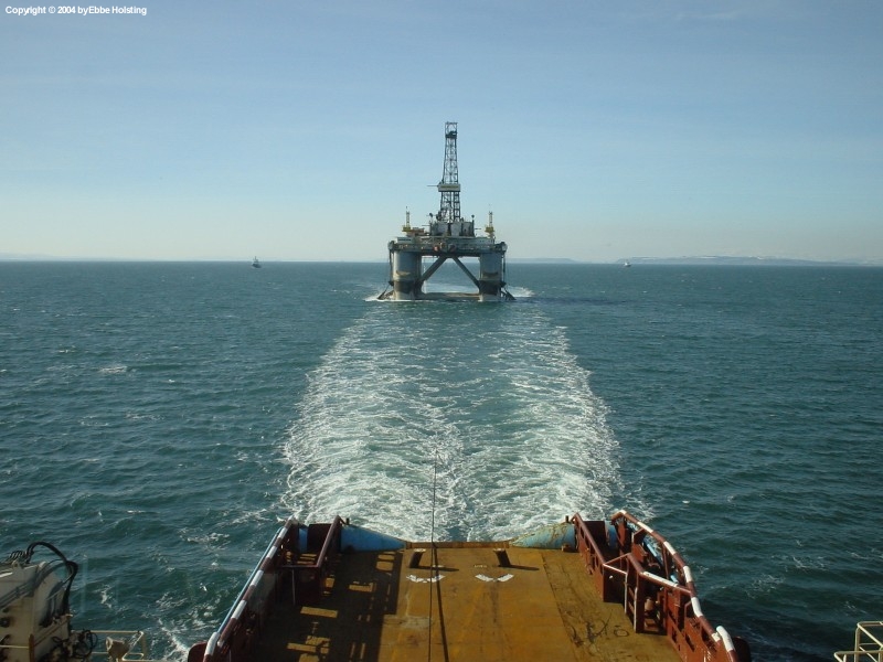
As the word suggests, a rigmove is the process of moving a rig from one location to another. That ofcourse also includes some sort of towing. Over larger distances a purpose-rigged towing bridle on the rig is used, and the vessel's work wire is connected to this. When towing it is essential to monitor tension in the wire in order to not overload it, especially in rough weather where shock loads can easily exceed the breaking load of the wire. Typically, shock loads are reduced by increasing the length of the tow wire, and in harsh weather tow wire length could be as much as 1500 meters! Here the weather is calm though, and the tow length it kept at a more maneouverable 600 meters. |
|
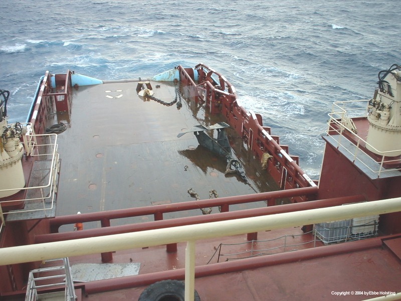
Rigmoves over shorter distances are sometimes carried out by towing the rig in one of its mooring anchor chains, typically if the move is no more than a few miles. Here, rig chain is seen running from the vessels winch and aft out over the main deck, through the guide pins. |
|
The aft end of an anchor handling vessel lives a hard life. Here we see the port side socalled "whaleback" from the aft. The steel plating is bruised, scratched and battered by the work over the stern, with steel wire ropes, anchors and chains all leaving their mark. This is perfectly normal, and the condition of the steel plating is continuously monitored, and repainted when possible. |
|
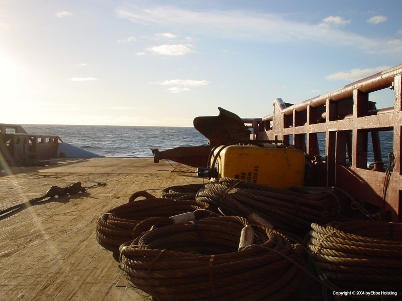
Extra equipment loaded on deck to cover any eventualities. Rig mooring equipment is subject to very harsh environments and need replacement regularly due to wear and tear. Is is normal during rigmoves and other operations to carry a small stock of spare equipment in case something needs to be replaced - or breaks during the work. The gear here is comprised of a number of extra wire pennants and an extra bouy. |
|
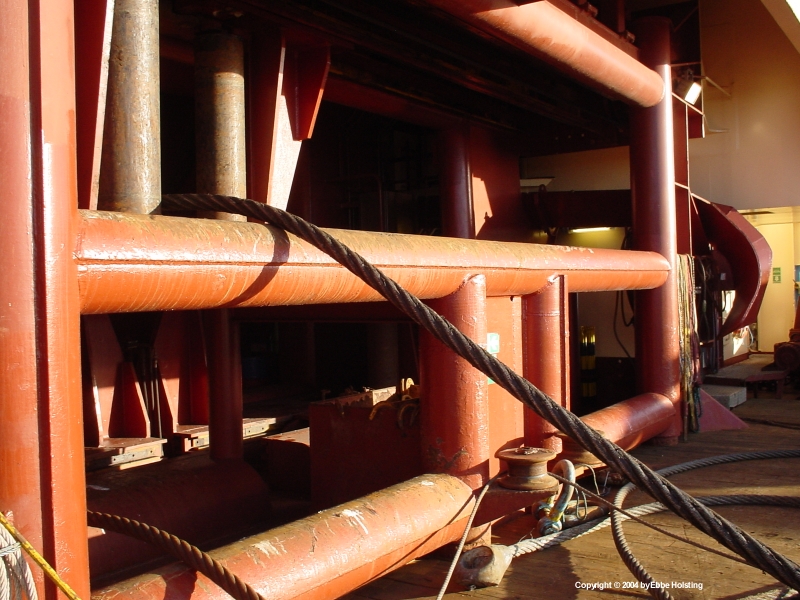
Towing wire under tension on the main deck. Safety during such work is of course essential, and no crew is allowed on deck when wires or other equipment is under tension. I took this picture from behind the cargo railing (aka. "crash barrier"), a zone typically considered safe during anchor handling operations. |